-
• Main Page
- • Home
• Antennas - • 144 MHz
- Straight Dipole
144 MHz YagisYBN 2-9m: 4.5 m moderate band width, low Antenna Temperature, good willing 50 ohms direct feed Yagi - a straight DE version twin to the GTV 2-9m
Elevation Plot
- GTV 2-2mA 50 ohms direct feed 2 ele. Yagi with bent DE and potential as broad beam Contest Stack.
It can be used as back-to-back stack:
- GTV 2-4w1.0 m 144-146 MHz wide band width version of the Low Noise Yagi with bent DE as useful for satellite operation as for contesting thanks to high F/B and small volume of rear quadrants lobs in general.
Elevation Plot at 144.1 MHz

- GTV 2-5m1.6 m moderate to wide band width version of the Low Noise Yagi with bent DE as useful for satellite operation as for contesting thanks to high F/B and small volume of rear quadrants lobs in general.
Elevation Plot

- GTV 2-6m2.4 m moderate band width version of the low impedance, yet 50 ohms direct feed Low Noise Yagi with bent DE introduced in Dubus 1/2013
Elevation Plot
- GTV 2-7w2.7 m wide band width version of the low impedance, yet 50 ohms direct feed Low Noise Yagi with bent DE introduced in Dubus 1/2013
Elevation Plot
- GTV 2-7n3.1 m narrow band, max. G/T version of the low impedance, yet 50 ohms direct feed Low Noise Yagi with bent DE introduced in Dubus 1/2013
Elevation Plot
- GTV 2-8w3.7 m wide-band, still good G/T and nice F/B version of the low impedance, yet 50 ohms direct feed Low Noise Yagi with bent DE introduced in Dubus 1/2013
Elevation Plot
- GTV 2-8n3.8 m narrow band, max. G/T version of the low impedance, yet 50 ohms direct feed Low Noise Yagi with bent DE introduced in Dubus 1/2013
Elevation Plot

- GTV 2-9n4.3 m narrow band, balanced between low Antenna Temp. and G/T version of the low impedance, yet 50 ohms direct feed Low Noise Yagi with bent DE introduced in Dubus 1/2013
Elevation Plot

- GTV 2-9m4.5 m moderate band width, low Antenna Temp. version of the low impedance, yet 50 ohms direct feed Low Noise Yagi with bent DE introduced in Dubus 1/2013
Elevation Plot
- GTV 2-10LT5.1 m moderate band width, lowest Antenna Temp. version of the low impedance, yet 50 ohms direct feed Low Noise Yagi with bent DE introduced in Dubus 1/2013
Elevation Plot
- GTV 2-11LT6.0 m moderate band width, lowest Antenna Temp. version of the low impedance, yet 50 ohms direct feed Low Noise Yagi with bent DE introduced in Dubus 1/2013
Elevation Plot
- GTV 2-12m mk2Improved 6.8 m version of the low impedance, yet 50 ohms direct feed Low Noise Yagi with bent DE introduced in Dubus 1/2013
Elevation Plot:
- GTV 2-12n6.8 m narrow band version of the low impedance, yet 50 ohms direct feed Low Noise Yagi with bent DE introduced in Dubus 1/2013
Elevation Plot:
- GTV 2-13m7.5 m version of the low impedance, yet 50 ohms direct feed Low Noise Yagi with bent DE introduced in Dubus 1/2013
Elevation Plot:
- GTV 2-14w8.4 m version of the low impedance, yet 50 ohms direct feed Low Noise Yagi with bent DE introduced in Dubus 1/2013
Elevation Plot
- GTV 2-16w10 m version of the low impedance, yet 50 ohms direct feed Low Noise Yagi with bent DE introduced in Dubus 1/2013
Elevation Plot
- GTV 2-18w11.7 m version of the low impedance, yet 50 ohms direct feed Low Noise Yagi with bent DE introduced in Dubus 1/2013
Elevation Plot
- GTV 2-19m12.4 m version of the low impedance, yet 50 ohms direct feed Low Noise Yagi with bent DE introduced in Dubus 1/2013
Elevation Plot

- Straight Dipole
GTV 2-16w Yagi with bent Driven Element
144 to 146 MHz Wideband Antenna Version (OWA style)
This Yagi has very low back lobes for its length. It may serve as a single powerful antenna for Tropo and EME
or make a quiet contest antenna due to its high F/B. The bent DE (K6STI style) transforms from approx. 17 ohms to 50 ohms at feed point.
Current distribution

2015-04-17: Nice photos of
 GTV 2-16w and
  GTV70-23 m at SP8MRD on qrz.com
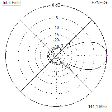
Performance Data
                       ele. 4 mm      ele. 8 mm
Gain vs. isotr. Rad.   16.9 dBi       16.9 dBi
Gain vs. Dipole        14.7 dBD       14.7 dBD
-3 dB E-plane          27.4 deg.      27.4 deg.
-3 dB H-plane          28.8 deg.      28.6 deg.
F/B                   -33.8 dB       -28.6 dB
F/R                   -27.5 dB       -27.4 dB
Impedance                50 ohms         =
Mechan. Length         9870 mm           =
Electr. Length         4.74 λ

Stacking Dist. h-pol.    DL6WU       max. G/T
top-to-bottom           3.62 m        4.45 m
side-by-side            3.87 m        4.60 m
Geometry

 Pos. 1/2 Length 1/2 Length Full Length Full Length incl. BC & SBC
in NEC in NEC Free Space Free Space on 25x25 Boom
Refl. 0 5xx.0 510.0 1025.0 1020.0 1029.9
DE(b) 215 100-4xx 100-491 982.0 982.0 991.9
DE(a) 274 0-100 0-100 100.0 100.0 100.0
D1 405 4xx.5 480.5 975.0 961.0 970.9
D2 690 4xx.0 474.5 963.4 949.0 958.9
D3 1236 4xx.0 462.5 942.0 925.0 934.9
D4 1874 4xx.0 455.5 930.0 911.0 920.9
D5 2615 4xx.0 448.0 917.0 896.0 905.9
D6 3407 4xx.0 444.25 910.0 888.5 898.4
D7 4227 4xx.0 438.0 898.0 876.0 885.9
D8 5072 4xx.0 436.0 895.0 872.0 881.9
D9 5927 4xx.0 433.5 890.0 867.0 876.9
D10 6762 4xx.0 429.0 882.0 858.0 867.9
D11 7585 4xx.0 427.0 878.0 854.0 863.9
D12 8404 4xx.0 426.0 877.0 852.0 861.9
D12 9190 4xx.0 423.0 872.0 846.0 855.9
D14 9870 4xx.0 416.0 858.0 832.0 841.9
ele. 1/4" ele. 8 mm ele. 4 mm ele. 8 mm ele. 8 mm
4 mm elements insulated through boom BC:
(1.) add the 2.3 mm of SBC as shown below
(2.) Use DJ9BV BC numbers and nylon rivets on square boom as shown on BC-page
(3.) ... or SM5BSZ's BC.exe for even more accuracy or other insulators
On Boom BC:
SegmentationBC = +2.3 mm = (144.7 MHz - 144.3 MHz) * 5.85 mm/MHz
BaseBC (25x25) = +7.6 mm for semi-insulated on boom
Total = +9.9 mm
Note: element lengths for Ø 8 mm fit 5/16" too
The Drivers diameter is 10 mm for all examples.
Use EZNEC's Auto-Segmentation at 350 MHz.
        Pos.    1/2 Length  1/2 Length    Full Length    Full Length    incl. BC & SBC
                  in NEC      in NEC      Free Space     Free Space      on 25x25 Boom

Refl.     0       5xx.0       510.0         1025.0         1020.0          1029.9
DE(b)   215      100-4xx     100-491         982.0          982.0           991.9
DE(a)   274       0-100       0-100          100.0          100.0           100.0
D1      405       4xx.5       480.5          975.0          961.0           970.9
D2      690       4xx.0       474.5          963.4          949.0           958.9
D3     1236       4xx.0       462.5          942.0          925.0           934.9
D4     1874       4xx.0       455.5          930.0          911.0           920.9
D5     2615       4xx.0       448.0          917.0          896.0           905.9
D6     3407       4xx.0       444.25         910.0          888.5           898.4
D7     4227       4xx.0       438.0          898.0          876.0           885.9
D8     5072       4xx.0       436.0          895.0          872.0           881.9
D9     5927       4xx.0       433.5          890.0          867.0           876.9
D10    6762       4xx.0       429.0          882.0          858.0           867.9
D11    7585       4xx.0       427.0          878.0          854.0           863.9
D12    8404       4xx.0       426.0          877.0          852.0           861.9
D12    9190       4xx.0       423.0          872.0          846.0           855.9
D14    9870       4xx.0       416.0          858.0          832.0           841.9
                ele. 1/4"   ele. 8 mm      ele. 4 mm      ele. 8 mm       ele. 8 mm

4 mm elements insulated through boom BC:
(1.) add the 2.3 mm of SBC as shown below
(2.) Use DJ9BV BC numbers and nylon rivets on square boom as shown on BC-page
(3.) ... or SM5BSZ's BC.exe for even more accuracy or other insulators

On Boom BC:
SegmentationBC = +2.3 mm = (144.7 MHz - 144.3 MHz) * 5.85 mm/MHz
BaseBC (25x25) = +7.6 mm for semi-insulated on boom
Total          = +9.9 mm

Note: element lengths for Ø 8 mm fit 5/16" too

The Drivers diameter is 10 mm for all examples.
Use EZNEC's Auto-Segmentation at 350 MHz.
Sketch of Driver Cell:

Pattern and VSWR Plots
Elevation and Azimuth plot at 144.1 MHz


SWR and Return Loss plots - simulated with 4nec2

Downloads
EZNEC file of this Yagi
EZNEC file of this Yagi as over stacked 4 bay (max. G/T)
Stacking

Stacking Dist.    DL6WU Formula    max. G/T
H-plane               4.21 m        4.45 m
E-plane               4.39 m        4.60 m
Elevation plot and data of 4 Yagi bay using DL6WU stacking distances

Gain vs. isotr. Rad.  22.85 dBi
Gain vs. Dipole       20.70 dBD
-3 dB H-plane         12.4 deg.
-3 dB E-plane         13.0 deg.
F/B                  -36.0 dB
F/R                  -28.9 dB
T_ant                221.4 K*
G/T                  -0.60 dB*
Theoretical numbers, no phasing line losses
nor imperfections caused by H-frame included
*) T_sky = 200 K, T_earth = 1000 K as in VE7BQH G/T table
Elevation plot and data of 4 Yagi bay using distances for max. G/T

Gain vs. isotr. Rad.  22.94 dBi
Gain vs. Dipole       20.79 dBD
-3 dB H-plane         12.0 deg.
-3 dB E-plane         12.2 deg.
F/B                  -34.1 dB
F/R                  -28.9 dB
T_ant                222.4 K*
G/T                  -0.53 dB*
Theoretical numbers, no phasing line losses
nor imperfections caused by H-frame included
*) T_sky = 200 K, T_earth = 1000 K as in VE7BQH G/T table
73, Hartmut, DG7YBN